This blog records building up the various parts on my Microtan Full-system back into a fully operating system, setting to work a 6809 Microtan system and more recently, the development of the Microtan-R system.
Full-system Rack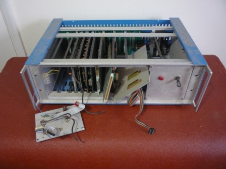
Found the original Power Supply in a box full of other PSUs. It's a 3U unit made by Bulgin, model ESM 30/ST12 (RS-591-764). The serial number is 179 - so not that many were made.
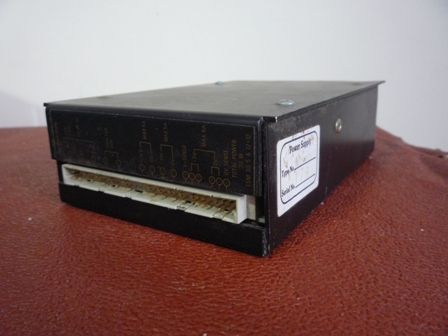
After taking out the cards and the rack from the case, slotted the power supply in and switched it on. The 12v line was OK but the 5v was well down. Decision time - open the PS and try to fix it or find another. I seem to remember the Bulgin struggled with a full rack so I'll go for the other option.
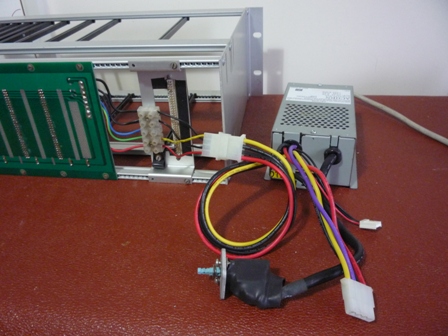
Found an old Acorn PSU. It's only 3.5A but will suffice for getting the system up and running with the MT65 and Tanex. Needed to change the Backplane power supply lines.
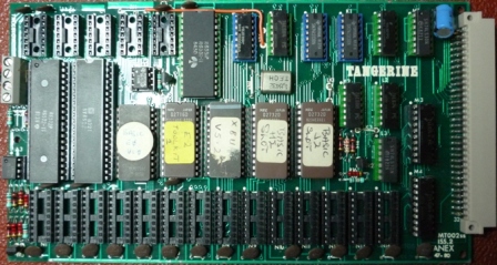
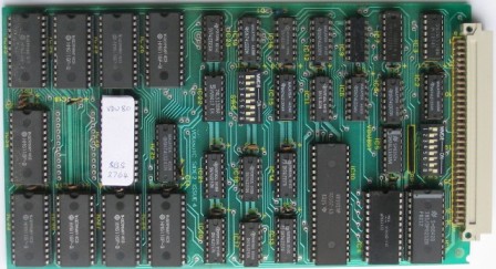
Next the MT65 board. This board had a number of mods to enable it work in the full system. Before trying out the board standalone, the mods needed looking at.
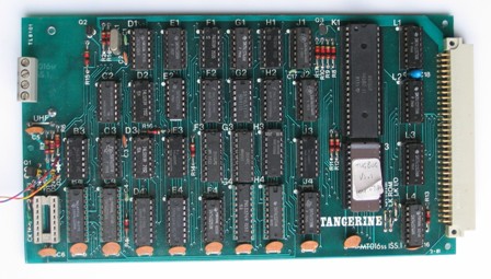
1. The monitor fitted is TUGBUG - not sure this works standalone, so replaced it with the original Tanbug 2.3.
2. The 3 wire links (LK RAM, LK ROM and LK I/O) all replaced.
3. Diode D3 was taken out to a switch on the front panel where video from the Video 80/82 module could be switched in. A signal diode was attached to the flying connectios
4. The UHF module had been taken off the MT65 and replaced with a terminal block. This is OK as the same monitor that takes the video/audio directly from the board is being used. The terminal block wire connections on the back of the board needed checking to identify the terminal block connectons.
Next fetch and connect up the monitor. Until I find the original keyboard, I can use the Micron keyboard.
Switch on power supply. Screen lights up with a matrix of chunky graphics. Press Reset, "TANBUG" written to screen. So far so good.
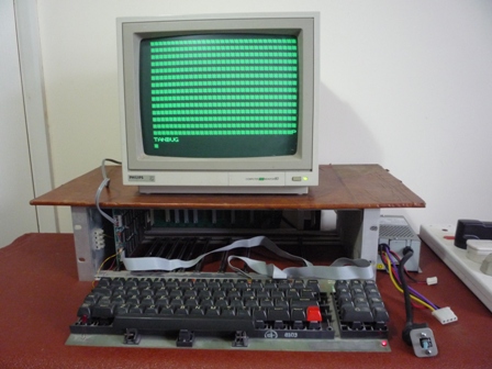
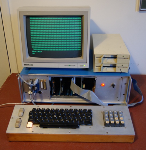
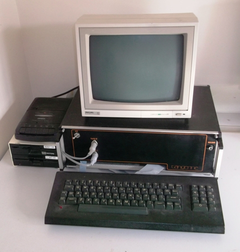
Simple test - type "L,0".Picture below showing starting point - stripped down rack with MT65 board, Philips monitor, Acorn PSU and Micron keyboard.
First job was preparing the MT65 for operating with the Tanex board by cutting again the 3 wire links (LK RAM, LK ROM and LK I/O).
Next, prepare the Tanex board which had no RAM and only the XBUG ROM:
Worked out that the orange wire mod enables both TTL and RS232 serial option output levels at socket E1. This should not not affect operation in this minimum configuration.
Other prep:
1. Re-inserted the 2114 RAM chips into the Tanex.
2. Made up an audio cable with two 3.5mm Stereo Jack Plugs for loading/saving files.
3. Inserted MT65 and Tanex into rack and connected video cable to monitor.
After switching on and resetting, got the familiar "TANBUG" screen output. Connected the playback audio cable via the earphone socket to the laptop. Typed in "F" to select "Fast" speed and then "F,MTEST" to download a memory test program. I used the windows application "Audacity" (http://audacity.sourceforge.net/) to "play" the MTEST program previously recorded from the Micron.
Program loaded successfully first time. So then ran it requesting checks of memory pages 2 to 1F.
It consistently failed at memory location 0445 - it appears bit 1 is permanently set. After referring to memory map, deduced problem chip must be the one in location N7. I swapped the 2114 chip at location N7 with the one at N1 and re-ran test. Test now consistently fails at memory location 1C45 confirming problem moves with this chip. I also noted bit 1 at locations 1C85, 1CC5, 1D25 etc were also permanently set. End result is I have a working TANEX up to memory location 1BFF. Faulty chip is not a problem as the 2114 chips will not be needed when I get the 64K RAM card installed.
Next test was to try recording files.
Plugged the record audio cable via the mic socket to the laptop.
Using the same settings (22KHz, 32 bit Floating, Mono) used for recording files from my Micron on my Linux PC, had only limited success - only files less than 2 seconds long. Recording levels drop if longer than this which then give parity errors on playback. Not sure whether this is laptop hardware or windows driver or application problem.Another problem also emerged, sometimes MT65 would lock up. Not even a reset works thereby a power down/up is required.
Next card installed was the TUG 64K RAM card.
Only one configuration change was required and that was moving SW1 switch 1 to position ON. This is because TANEX still has RAM fitted in locations 400 - 1FFF. SW 2 switch 7 needed to remain ON to avoid the card overlaying the memory area taken by XBUG fitted on the TANEX.
Plugged the card into slot 4 (Slot 3 has unique wiring connections for the Video 80/82 Card). Switched on power and loaded up the MTEST program. Ran the test from Page 20 (start of memory being used on the 64K RAM card) to Page BB (end of the memory before the IO locations). The test continually failed (right at the start) and locked up. Problem appeared to be same as Job 4. This needed to be fixed before being able to proceed any further. See "Job 4" below.
Having fixed the lock-up problem, reloaded MTEST and re-ran the memory check from Page 20 to Page BB. Passed! Also ran the test for the ROM memory area from Page C0 to EF. This also passed - no errors.
Finally, removed the RAM from the TANEX board, switched SW1 switch 1 back to OFF on the 64K RAM card so that it would overlay the TANEX memory area and re-ran the MTEST program checking pages 04 - BB (Program area) and C0 - EF (ROM area). Noting Pages BC-BF are the IO locations and Pages F0-FF are taken by TANBUG and XBUG.
Now I had a decent Micron system (MT65/Tanex/64K RAM), the next task was refurbish the front panel. I wanted to bring out dedicated sockets for the serial and printer ports so the better thing to do was insert new sockets rather use the existing ones and then find later I needed them.
Picture below shows the finished job.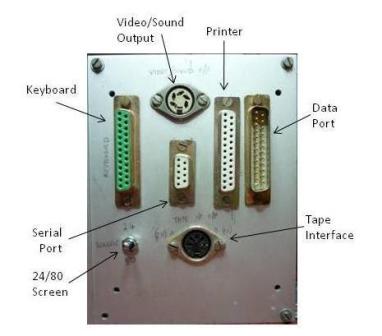
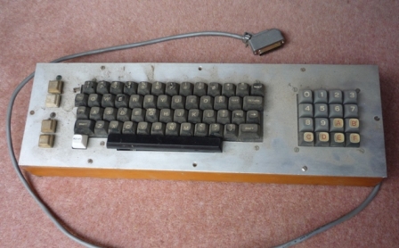
The connections to the sockets were in poor state so all of these were re-soldered and new links for two new sockets made up to 14 pin DIL headers. Now I had the front panel back in use, I could dig out and use my original keyboard. It was very dusty but otherwise in good condition (photo below).
After connecting the Microtan up again (and solving a few minor problems), it all worked OK.
It took a fair amount of effort to get to this stage so before going any further I wanted to document all the connections made to the front panel in case needed for future reference. This is being done in a spreadsheet and when finished will be inculded in the 'Full System' section.
Next target is to fit the EPROM Storage Card (ESC) aka COMBO board as it can be configured alternatively as a 6116 RAM card. This card holds my firmware (eg BASIC, DVWORD).

I first needed to replace TANBUG 2.3 with TUGBUG 1.1 on the MT65 board to take advantage of the built in access and tranfer routines. Fitted this and re-ran the MTEST program - no problems.
Plugged in the ESC, switched on and tried out the following routine to transfer Basic and the Toolkit from the ESC into RAM locations C000 - EFFF
R0,2FFF,0,C000
This failed. Closer inspection revealed a hardware problem with the ESC card. Further investigation indicated a problem with the CMOS device IC5. This needed replacement. I therefore decided to put the ESC to one side for repair.
So instead of loading BASIC into RAM C000-EFFF, I removed the 3 EPROMs from the ESC and installed them in the TANEX board.
This needed the configuration of the 64K Ram card changing it so it no longer appeared in the memory locations C000 - EFFF. Switches 2.1 to 2.6 were switched ON.
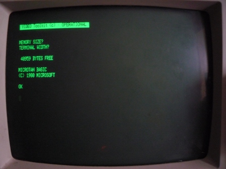
On powering up, I got the familar "Monitor" prompt on the screen from the TUGBUG. I noticed my home-built keyboard was becoming intermittent ie not recognising the first key press after a reset. Swapping it with my Micron keyboard allowed me to continue.
I then ran MTEST from Page 2 through to Page BB successfully confirming the 64K RAM was behaving as it should. However, when I tried entering BASIC by typing 'BAS' or GE2ED, the Microtan crashed out. By EPROM swapping I determined that is was the extended BASIC EPROM in socket D3 that was causing the problem.
After typing 'BAS' and a couple of returns I got the reassuring message that BASIC had 47103 bytes of free memory. In other words it was recognising all the memory on the 64K RAM card.
Time now to get the Disk interface up and running. I plugged the Tandos card into the right hand slot of the rack.

Originally I had a Watford Electronics 40/80 track floppy disk drive (Mitsubishi TS3126) in its own case along with a mains power supply. The case was built for two drives and I later fitted it with one of the Amstrad 40046 40 track drives from my first PC - the Amstrad 1512PC.
It then took a full day to find a combination of drives, floppy disks and their associated SYS files to get a working combination. This was using the two Amstrad drives. The system disk had the following configuration:
Unit : TracksA number of my old disks were unreadable but even with those they were, the Tandos system was still not 100% reliable in reading and saving files. More work is required.
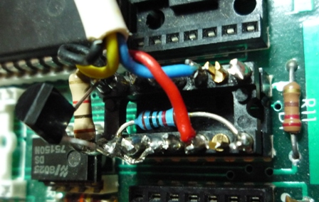
This weekend was spent getting the serial option to work in the full system. The issue is that TUGBUG in the full-system checks to see if a tele-type printer is connected to the serial port during initialisation. If it sees no connection or DCD and DSR lines low, it sets the UART baud rate to 110 baud and enables interrupts. This will ramdomly crash the system. The no connection issue is solved by pulling these lines high via a resistor - see Job 4. This was not an issue with my Micron as it is fitted with TANBUG v1 which does have the functionality to operate with a tele type and so does carry out this initialisation check.
The issue for the full-system was resolved in two parts a) add circuitry to enable TUGBUG to accurately detect if there exists a serial connection and the application at the other end is "connected" and b) amend the inialisation routine to set more appropriate baud rate and not enable any interrupts.
With the serial option set up described here, the DTR signal line from the laptop goes from 0v to 5v when the terminal application on the laptop "connects". It reverts to 0v when it "disconnects". So the UART on the Tanex normally needs its DCD/DSR/CTS inputs held high accept when the incoming DTR signal is 5v. This circuit was adopted.
All the components were mounted on the 16 pin E1 header. The two spare pins used as seats for the 1K resistor and transistor.
The TUGBUG serial option initialisation routine is located at F86E. The following changes were made:
F87C changed from 93 to 1F (sets baud rate to 19200)
F888 changed from 89 to 0B (keeps interupts disabled)
F88D changed from 21 to 20 (sets only serial printer flag, not the serial keyboard flag)
A new TUGBUG EPROM was blown with the TUGBUG v1.2 designation.
With all the changes the full-systems operates fully when connected via a serial lead to a laptop running Hyperterminal. When the Microtan is reset, it correctly recognises if Hyperterminal is connected and the screen output is displayed in the Hyperterminal window. From there the output can be formatted, saved or printed. At any time the output to the laptop can be toggled on or off by typing "CNTRL V" on the Microtan keyboard.
May 2020 update. A couple of years ago I wrote some general notes describing how to connect a PC/Laptop to the serial port using the TeraTerm terminal program. I thought these notes were referenced here but found I hadn't updated the web-page. This has now been corrected - they are here.
After fitting a new IC5 from Ebay into the Eprom Storage card, I pushed the card into the rack again, switched on and tried out the following routine to transfer Basic and the Toolkit from the ESC into RAM locations C000 - EFFF
R0,2FFF,0,C000
It still failed. It looked as if the problem may lie with one or both of the 6821 Peripheral Interface Adaptors. These are fitted on the ETI Sound Card as well, so I decided to get this up and running first and then swap components with the ESC to isolate the problem.
I made a connection using audio coax from the Sound Card to the Video/Audio socket on the front panel and plugged the card into the system rack. I still had the twin coax interconnecting cable between the front panel and the Philips monitor so connected that up as well.
I now needed to program the sound chip Registers to generate the different audio waveforms. I found some machine code ("SNDBD") I had that was converted from the Basic code provided in the ETI article notes. This included user interface code to prompt the user for a Register Number, then display the current value of that register, then prompt for the new value, similar code to that of the Tanbug 'M' command. It also had a routine to transfer values from memory into the sound chip registers. All I needed now was a series of register values to produce meaningful audio. These I lifted from my old 'Space Evaders' program and included them in a new version of the program "SNDBD2". Details and copy of the code are contained in the Software section here. All ran fine giving Deep Beats, Dinking, Crash, Tone and All-off audio.
Now having repaired the EPROM storage card (ESC), I loaded it up with all the EPROMs I had
containing code operating in the C000-EFFF RAM range. These are:
BASIC
DVWORD
FORTH
ASM
My intention for the Full System is to load code for this area from the ESC and for code in the 400-A7FF range, from the Tandos system. DVWORD would have to wait until I get the Video80/82 Card up and running. For FORTH and ASM, I set about writing a short program that is held on disk to load the requisite code from the ESC into RAM and then run it. For example, the FORTH code is loaded from the ESC storage area 5000-6FFF into RAM at C000-DFFF using the TUGBUG F832 and then jumps to C000. This program is then saved to disk with the Filename FORTH so that at any time I type "FORTH" the code is fetched and the program run automatically. For BASIC I did something similar but instead of creating its own file, I inserted the code in front of the 'DBASIC' disk utility program and copied it back onto disk. Copies of these programs are held in the Software area.
After a number of weeks, I finally got the Video 80/82 board up and running.
This had proved to be the most difficult component to get going so far. Even in the '80s this board showed occasional signs of instability it was still very useable. When I first tried in the rack, there was much more instability on the display. After pressing RESET, there were marks appearing and disappearing again all over the display. Only sometimes did the 'VBUG' message show at the top of the screen and this was not really readable. In the second quarter of the screen downwards there was much more activity strongly suggesting a secondary problem. I did some visual checks, continuity checks, resoldering all joints and even component substitution. This ended up making the overal problem worse to such an extent that the card could not be reset at all and the rest of the system would not boot up. Something was seriously wrong and I was becoming concerned that repeated inserting and removing of the card would impair the 6way plug and sockets. I therefore put it to one side and concentrated on getting other system cards operational again.
To get round the need to keep plugging / unplugging the card into the rack, I built a simple card extender using odd bits of vero-board back to back.
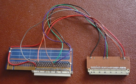
To prevent damage to the rest of the system I did not connect the address and data lines, just the following to enable the 'RESET' picture to be displayed on the screen:
Power 5v and 0vDiagnosing what was going on was much easier with the powered up card laid out on the table in front of me. Then a break-through; when I happened to place a sheet of of my notes on top of the card, I noticed the second quarter of the screen change dramatically. This was easy to track down the culprit being the IC33 socket not making good contact with the IC33 pins. This was one of those sockets you could remove the plastic body away from the pins. Some 're-positioning of the spring contacts before replacing the plastic cover solved the problem.
Because the card would not reset my next area for investigation was the Processor, its EPROM and RAM. Changing the 6502 made no difference. It was then when locating the Processor RAM on the card I had my second break-through. This fault was entirely down to me. At some stage I had exchanged one of the 8212 chips with an 6116. Placing them in their correct slots cured the 'no-reset' problem and I had immediately a stable 40 column picture on the screen. During my earlier investigaions I had obviously set the DIP Switches to 40 column mode.
However, when I switched the card to 80 column mode, the picture was a complete mess - no stability at all. This pointed to a problem with IC 07 (74LS123) which provided the (double) clock rate. It was also noted that the circuit diagram I was working to needed updating.
Fortunately I found an old 74123 I had (although had to clean the solder of the legs). Plugged this in and again immediately a rock-steady 80 column picture - much better than it has ever been. So what had taken many hours of investigation, the 3 issues where solved in just a couple hours.
All left to do was to re-insert into the system rack and place the BASIC E0/VDU Toolkit EPROM in the Combo card and fully operational again. Just need to patch the EPROM at E0C9 to auto-start the toolkit some time.
These last 2 wet cold months I've spent my spare time recovering the Tandos discs I had. I soon found I didn't understand a) the Tandos Discs Commands or b) the actual data structure on the discs themselves. So I set about creating a couple of documents that captured all I needed to know in a very useable form. These are Tandos Commands and Tandos Disc Structure.
My original discs were in a poor state. This was due to
To check the integrity of each disc, I developed a program that inspected and recorded each track/sector and the linkage between them. The program is called DSKCH1 and an example of its output is given in DISK3CHK.pfg
My attention was now drawn to the repair of a Micron. By substitution into a working system, it was clear there was no major issue with the Tanex, except one of the VIAs was not working. However the MT65 board would not even reset. It turned out that the board must have sufferred a major zapping as several chips were found to be unserviceable. These replaced chips caused the following symptoms:
Once that was repaired, I looked at setting to work an Vero branded ascii keyboard I had acquired. The problem was that the keyboard outputs did not match the keys pressed. This was even more complex to resolve as it had two levels of encoding. The first was by the keyboard encoder chip. The second was by a 2716 eprom. By much trial and error I determined the first level encoding map. It was then a relatively straight forward task to determine the required second level coding such that the output matched the keys pressed and program the EPROM accordingly.
My project for November was to create a process for generating DASM source code from a code listing produced by the XBug Interpreter. The process involved:
Good progress was being made until everything had to be packed away in preparation for our house sale. This project will have to wait until after the house move and I can find time again to spend with the Microtan.
Finally found some time to continue with the project started last November. This is now complete. The notes capturing the process are MakeSource.doc. The Excel spreadsheet template used is MakeSource.xlsx
Ten years ago I uploaded my first page of information to this web-site. I couldn't let such a special milestone slip by without comment. Since then it has grown significantly and because I have collected so much data, it has been extremely useful to me for finding particular information when required. None more so that the Knowledge database. There is so much helpful information in all the various newsletters published in the 1980s, there was always the problem of finding it, or even just being aware such help or information existed. Time and time again I have been able to immediately identify and access it. I am also really pleased to have heard from other Microtan owners who have found the site both useful and interesting.
Over this 10 year period I have also collected much more hardware and software so again the web-site has provided a single reference centre for all the supporting information. The time invested in populating the site has proved to be extremely beneficial. I use it all the time and since moving house at the begining of this year, I have not had the need to unpack the paper hard copies of the information stored.
Looking forward I still have plenty of projects on the go or in mind. In the immediate term I want to continue getting familiar with Forth and tailoring the version I use 'DFORTH' to my system. Also to continue setting to work my 6809 Microtan and capturing the supporting documentation on this web-site. Now I have an original 'Tangerine' system rack I want to re-house my Microtan 65 full-system into it to give it a more authentic look. I am not sure where to go longer term. Certainly the web-site needs a complete overhaul and I still have items of my system I want to get up and running and document more fully. I would also like to find time to delve into the world of PGM graphics. I just hope I have the continued health and interest to keep it going for another 10 years.
Over the Christmas / New Year period I set about rebuilding the Microtan 65 Full System to give it a more authentic look. This involved mainly swapping parts with the Ralph Allen 6809 system. The items swapped were:
One of the Tape connectors on the front panel was wired to provide Video and sound connections. The Microtan front panel has a hole available for the TV connection from the MT65 board. This was used to mount a switch to enable selection of either a Microtan video screen or Video 80/82 screen.
The old system looked like this:
The new-look Microtan looks like this:
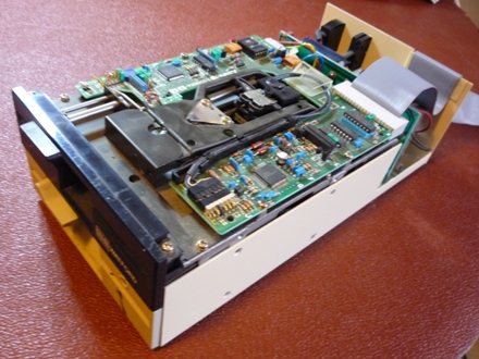
For some months whilst looking into understanding more about the TANDOS system and increasing the reliability of the Disk Drives, I came across an amazing Floppy Disk Drive Emulator. It is called the HxC Emulator and can emulate a whole host of floppy disk drives including those using the Shugart interface like the TANDOS system. It is featured on the Web-site http://lotharek.pl/.
So a couple of weeks ago I purchased the 'Slim' version and installed it into the Full System. After overcoming an initial problem with the SDCard, it works a dream. Now housed within the 19" rack, there is no need for external drives and I have the bonus of having increased, reliable capacity. Full details are here.
Spring and Summer days - not much time for playing with the Microtan. Still, I have managed to build and fit a new power supply for the Microtan. See Job 01. The Ralph Allen PSU has now been returned to the 6809 system.
I have also been helping two other enthusiasts with their projects. Firstly Chris Shaw, who is generating modern CAD type schematics for the main Microtan circuit boards. I will addthese to this web-site. Secondly, David Fry is generating a replacement Microtan 65 Printed Circuit Board. This will have a modified layout but will mostly use the same components as the original MT016 board. It will have a different modulator and an EPROM instead of the character generation PROMs.
Another year has passed! The last few months I have been working with David Fry on the Microtan-R project, helping to define and test the PCB designs. The first PCB that David generated was the MT65 CPU board. I found that all the components required to populate this board were readily available via the internet. The first version of the MT65 CPU board had a couple of errors so David generated a second version (v1.0b) which corrected the errors and included a couple of enhancements. The KiCAD files for this latest version have now been released on this site and I have since had a batch of this PCB manufactured. I built up one of these boards from scratch and transferred the ICs from the first board to this latest version. It appears to function completely as expected. Once fully tested, I shall offer the surplus boards for sale.
David has also generated a keypad that is functionally the same as the Tangerine Keypad. I have built and tested one of these keypads. The KiCAD files are also available on this site.
To house the Microtan-R project, I have cut down a 4U 19" rack to the same size as the rack I use to house the 6809 Microtan. I shall now set about building a power supply unit to fit into this rack.
The next PCB that David is developing is the motherboard to fit into the 19" rack. This will be similar to the TUG motherboard but will have less expansion slots (to keep costs down) and wider gaps between the slots.
Now the second version of the Microtan-R CPU PCB has been proven, I am now offering these for sale in the Shop. The first-off Microtan-R motherboard is also now in production. This is similar to the Tangerine motherboard but has no on-board signal buffering or block enable capability. It has a CPU, TANEX and 5 Expansion slots.
Earlier this week I was generously given a box of Microtan items (hardware, software and documentation) by Chris Priest, a programmer and ex-Microtan user. Over the coming weeks I hope to document the items I haven't come across before on the web-site. Two items in particular caught my eye; a Bulldog sound card and an Oric Talkback speech synthesiser. The new Microtan-R system rack will be very useful for setting work these and the other cards in the collection.
For some time I have been wanting a logic analyser to help test and diagnose Microtan circuit boards. Quite by accident I came across one described on the web that uses an Arduino. So this weekend I set about putting one together and trying it out on a Microtan CPU card. The details are here.
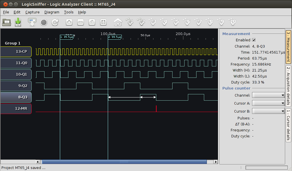
Below is a screenshot of the analyser at work recording the signal levels on one half of the J4 74LS393 chip. J4 takes a 3MHz clock from the oscillator circuit and divides it down to 187.5KHz in one half. This is further divided down in 4 stages in the other half under test. However the output from the last 2 dividers are AND gated together to reset both sets of dividers, ie after 12 clock pulses. This creates an output at the last stage of around 15.6KHz with a 33.3% duty cycle which is used as the Horizontal Blanking signal on TANBUS 18a pin.
The arduino logic analyser certainly has its limitations but it will do fine for me for use with the Microtan. Costing around �5, I doubt I am going to find better value. I think I will configure one permanently as a Logic Analyser, buy a case for it and keep it in my toolbox.
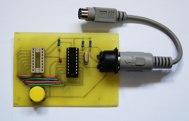
It's been a while since my last entry. I have been mainly helping other users with their projects, not least the Microtan-R project. One thing I have done recently is build a prototype PC-AT Serial-ASCII Keyboard Converter as presented by Danny Page here. This entailed compiling the PIC 16F84 code, programing the PIC and constructing the PCB. The finished job is shown in the photo below.
After using the interface with a PC-AT Keyboard for a while, I soon realised a couple of shortcomings in the code. Firstly it did not handle Control Key pressed or Caps Lock set correctly. Furthermore, if the Reset button was pressed when the Caps Lock (or Num Lock or Scroll) was set, then the keyboard LED indication became out of sync with the program. These have now been addressed in Version 2 of the code.
Further update (11 Oct 16): a version 3 of the code has been released where the converter sends a CAPS LOCK 'on' signal to the keyboard following a RESET. More details are provided in the Project Notes.
The programmed PIC and professionally manufactured PCBs are now available for purchase from the Shop
A busy few months helping David Fry develop and test both the Prototype and Production Tanex-Plus boards for the Microtan-R system. I am happy to say that this work is now complete and the PCB and programmable memory chips are available for sale from the Shop
The testing of the Tanex-plus revealed an issue with the MT65-R CPU Character Generator EPROM. The original Character ROMs ignored the 8th bit so in the MT65-R CPU design, the opportunity was taken to enhance it. Setting the 8th bit produced an inverse-video representation of the characters. When trying out FORTH with the Tanex-Plus, I discovered that 6502 FORTH programs have the 8th bit of the last character of their stored 'Words' set to denote the last character of the Word. On the MT65-R system, this results in a slightly odd display of the stored Words following a VLIST command. This did not however affect the running of the FORTH program. A Rev 2 version of the Character Generator EPROM has been produced that overcomes this by repeating the lower 2k of code in the upper half. This version obviously has no inverse-video capability.
Other news is that David has designed a new layout for the Serial Keyboard interface PCB which enables it to be manufactured professionally as mentioned in the previous post. This may be useful for Users having difficulty sourcing a suitable ASCII keyboard for the Microtan.
With help from Martin Bolding, over the last couple of months I've been reconstructing the circuit diagram of Tangerine's High Resolution Graphics (HRG) card from photographs of the top and lower surfaces. This proved to be more tricky than I expected as the board had been derived from the original Issue 1 board. Consequently some copper tracks and their connections to components were not necessarily where you would expect to find them. Anyway I have generated a circuit diagram and a description of how I think the circuit works, both of which are on the Products page here. Note that this circuit has not been tested. If anyone spots anything that does not look right, please let me know.
Back in the 1980s, I was particularly interested in an article in Electronics Today International magazine describing the construction of a Microtan based Space Invasion game. It stated that an EPROM was available to buy to run the software on a Microtan fitted with a Microtan keypad. As I did not have the money to buy the EPROM or the Keypad, I did not think any more of it. However some time later the hex dump of the software for the original game appeared in an ETI sister magazine. I embarked on a major project to re-assemble this code using a bespoke keypad (that plugged into the Tanex 6552 port) and the ETI Sound card. I first entered the code into my Microtan. Then using the Tanbug "I" command, printed out the whole dis-assembled code on my Sinclair printer (with the metalised paper). I cut the strip up into blocks, stuck them into a note book and set about understanding how the programmed worked, making notes as I went along. I had no assembler at that time so the new program was generated by moving the original code around using the Tanbug "C" command and inserting the new code for the keypad and Sound card using the Tanbug "M" and "T" commands. This program still works today. Some time ago I was given the Eprom image mentioned above which I made available in the software section of this web-site.
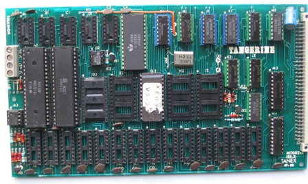
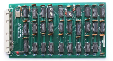
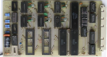
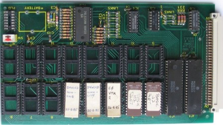
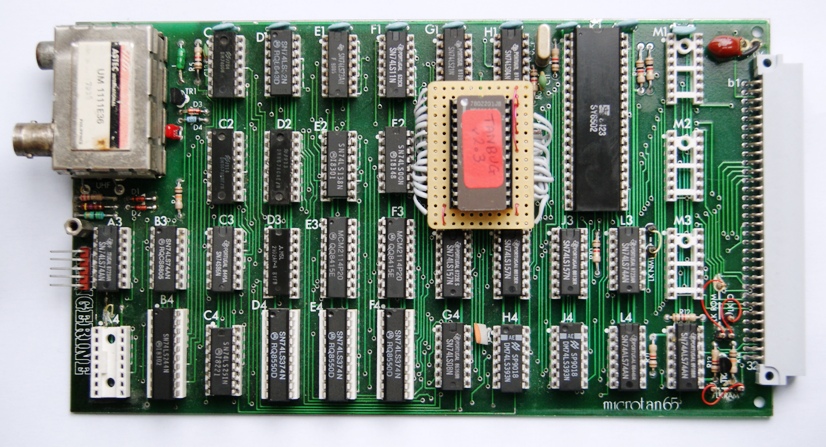
Coincidently there were 2 emails relating to this Microtan game waiting for me when I returned from a few days away last week. One was from Ian Castle who sent me 4 photos of the prototype printed circuit boards used by Tangerine to develop the Space Invasion game featured in the ETI article. He was given the boards by a friend who had worked for Tangerine at the time.
Processor BoardThe second email was from Barry Graham who had a problem with the Space Invasion image he had blown onto an EPROM. So I did the same and tried it out on a MT65 CPU + Tanex setup. The image itself appeared OK so I generated and sent Barry a 'first-pass' listing of the dis-assembled code which I had annotated with some notes from my original project. This enabled Barry to resolve the problem.
Now I know the Space Invasion eprom image works, I have included it in the Tanex Plus U13 image. It appears in the Page 1 $E800 - $EFFF slot. I have also created a version that runs in RAM starting at $400. The program details and downloads are in the Software section.
It was while I was re-assembling the Space Invasion EPROM code to run in RAM that I came across a bug in XBUG v5.2. I discovered that the instruction "STA Operand,Y" threw an error. When I tried this using the Microtan Translator (Monitor "T" command), it again threw an error. I tried every XBUG I had and they all had the same result. I looked through all the documentation I had including the magazines and could not find any reference to this issue. It is really odd that this has not been discovered before. If anyone has an XBUG that correctly translates the above instruction into opcode 99, I would be very interested to hear from you.
The bug has now been fixed in a new XBUG version which I have named v5.3.
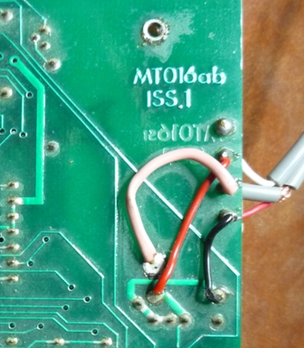
I have just completed the modification described in Tug News 13 on page 8. This modication replaces the two 1K-monitor proms on original issue Microtan 65 CPU boards with a 2K 2716 EPROM. This allows the TANBUG v1 monitor program to be upgraded to v2 or v3 or to TUGBUG. The 2 proms are removed and replaced with a 2716 module. There is also a small change on the back of the CPU board to reroute one of the old prom pins from address line A9 to address line A10. The track from G2 pin 15 to H2 pin 15 is cut close to G2 pin 15. A wire link is then soldered from G2 pin 15 to K2 pin 39 (A10) and held in place with a spot of glue (see photo).
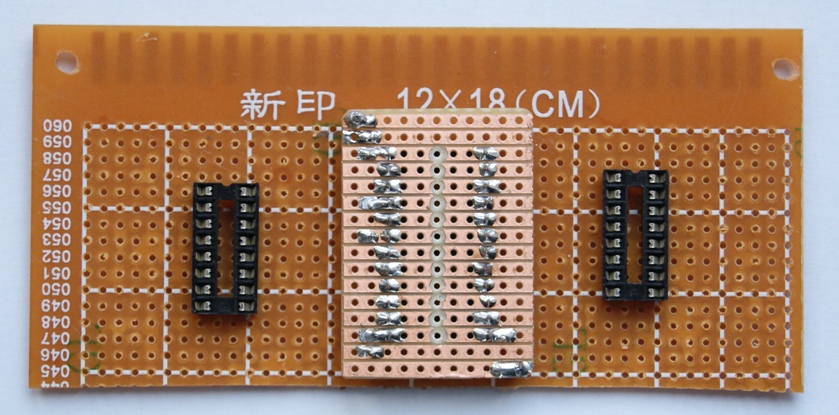
The module consists of a 24 pin DIL socket mounted on a 16x11 piece of veroboard. This is connected via ribbon-cable wire-links to two 16 pin DIL headers which are plugged into the two prom sockets G2 and H2. This exercise is quite fiddly and I found the need for a jig to hold the veroboard module and two headers in place. This I constructed out of a scrap piece of veroboard (photo). The module was held face-down in the centre of the board by soldering two wire links in opposite corners. The two 16 pin DIL sockets to hold the headers in place either side were held by soldering two pins in opposite corners to the board. I generated a new diagram to aid the wiring up of the module. When complete, the two 16 pin plugs were lifted out of their sockets and the 2716 module de-soldered from the jig, turned over (faceup) and the two 16 pin DIL headers folded back underneath it. The module was then carefully plugged into the CPU board so that the G2 header plugged into G2 socket pins 1-8 and 11-18, and the H2 header plugged into H2 socket pins 2-9 and 10-17.
While waiting for the last few components before starting the assembly of the newly-arrived TANDOS-R PCB, I thought it a good idea to document a procedure for creating a MASTER TANDOS system disk. The problem being, to create a new system disk, an existing system is required. There are 2 steps required; first create a formatted and initialised floppy disk, and then save the TANDOS 'S' save program onto the disk so that the other command programs can be saved onto it. In both cases, an existing system disk is required. There are 2 ways I could do this; write or amend existing software, or use the existing software then hack the data stored on the disk (with a disk sector editor) to make the disk useable. I opted for the second option as it would be much quicker to do. Even though further steps were required than originally thought, it was not long before I had creating a new system disk from scratch. However writing up the procedure took far longer than generating the system disk in the first place. This was because it was necessary to be very clear and detailed in describing the various steps involved and it had to be written for someone who had never used the tools or techniques before.
In working through this option, I had developed an understanding of how the existing CREATE and DSAVE programs needed to be amended to format/initialise a disk and save a copy of 'S' on it. Maybe a hack of the existing code rather than rewritting them would do the job and not take so much time afterall. I shall look into this, but in any case, I shall still make available this procedure, as it provides an excellent insight into how TANDOS saves and uses data stored on floppy disks and an opportunity for a user to become familiar with the disk sector edit tool.
21 Feb 18. I have now completed this and updated the TANDOS Software section here to include both procedures.
Microtan enthusiast Barry Graham has been busy. He has recently built the TANDOS-R board to operate with the original Microtan boards he rediscovered last year. He then pioneered the work to interface this board with standard PC 3.5 inch Floppy Disk drives. This he documented in TANDOS-R Manual Appendix C.
Next he successfully transfered the games on Geoff MacDonald's Microtan Emulator site to run on his 'real' Microtan. This was achieved by swapping his TANEX E2 ROM with a RAM chip so that the XMOD Serial transfer program XMODF0 (details here) could be loaded and run from there to transfer edited .m65 files into the TANEX RAM. The games were then saved as .wav files. Details of these games are contained in the new "Games" section with information how these files may be downloaded. Note all these games require a joystick connected to Port A of the first TANEX VIA - details here.
Barry's web-site is microtan.thegrahamfamily.me.uk
It includes details of his Character Generator ROM replacement, 64K Ram replacement board, Joystick interface and system and keyboard case projects.
In the last 12 months I have been progressing two significant Microtan Projects. One is the production of a replacement for the Tangerine High Resolution Graphics (HRG) board, the other the restoration of a full mainly TUG based system. The former is complete and PCBs for this HRG-R board are available in the Shop. However I have since being trying to create a single utility program that will load up BASIC and at the same time configure the system to recognise and process both the additional TANDOS BASIC commands and additional HRG specific BASIC commands provided by the HRG Toolkit. I tried at first to find a solution that did not involve any modification to existing BASIC/TANDOS/TOOLKIT code. Unfortunately this did not work and the best solution that I could up with involved a small change to the DBASIC code that resides in the TANDOS EPROM on the TANDOS board. The tricky part in finding a solution is configuring the BASIC self-modifying code in zero page which is used by BASIC to identify and process additional (new) commands. The code needed to be changed so that it would identify and process both TANDOS and toolkit additional commands (not just one of them). So I do not forget what I learned, I generated some notes how this area of code operates and how it can be changed to solve this problem. The full details of the BASIC/HRG utilty program is captured in the HBASIC document.
My other project is still being progressed. It has enabled me to provide more information in the Products area of this web-site, particularly regarding the Programmable Graphics Module. In turn this has enabled me to get my own PGM operating in my Full system.
Over the weekend I did a stocktake of all my FORTH resources. I found I have 3 different versions of program for the Microtan but no manual and 2 manuals but no program.

If anyone has, or knows the whereabouts of the missing items, I would be very pleased if you would let me know. As a stop-gap I've started creating a 'Getting Started' document for those programs where I have no manual. I've also updated the Software/FORTH section of the website.
It was when I was trying to make a working disk for the DFORTH program I discovered that the TANDOS Disk utility 'FORMAT' doesn't work. I therefore created a new version (Doug Deedman's in Microsoft World, Volume 2, Issue 2) which does work. This new version is available in the Software/TANDOS section of the website.
I also found the easiest way to enter FORTH Screen data was to enter the FORTH EDITOR and then send a text file containing the screen data from a PC/Laptop via an RS232 link. Details here.
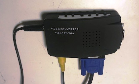
For some months I have been using a flat screen VGA monitor (together with an S-Video to VGA converter) instead of an old TV to display the Microtan-R screen. Generally this has worked well although the converter is not so tolerant as the TV at initial syncing. To get round this I always turn on the Microtan before the converter. However a new problem arose recently when displaying the HRG-R video. If in the program the screen is cleared completely (no graphics, no text, no mixed video) then the converter loses sync and fails to display anything. The only way round this I've found is to plot a single point with the !10,255,0 command immediately after clearing the screen. This gives the converter something to latch onto. Once the display has other content on it, the point can be reversed uses the !11,255,0 command.
After the development and production of the HRG-R, I wanted to conduct a few experiments with the HRG toolkit, in particular, using paged RAM memory. Paged memory allows multiple 'pages' of memory in the range $2000-$BBFF to co-exist in a system, any one at a particular time being selected for either read or write operations under software control. On the original Tangerine system, the logic for selecting different RAM memory boards is located on the Tangerine motherboard. There are a couple of problems trying this out on my Microtan-R system. Firstly, the motherboard does not include the paged memory circuitry. The only original Tangerine motherboard I have is fitted in my Microtan 6809 system and I wasn't keen on dismantling that. Secondly, TANEX-Plus has fixed, permanently-enabled RAM memory from $400 to $BBFF and is therefore incompatible with using paged memory. This could be easily solved by substituting the TANEX-Plus with an original TANEX and placing a TANRAM board in one of the spare slots.
So the solution was to develop a new motherboard for the Microtan-R which replicates the original Tangerine one. My prototype was simply an extension of the Microtan-R motherboard, adding the paged memory and extra buffering circuitry to the left of the CPU slot and adding a few more expansion slots to provide 8 + 1 "EXP" paged memory slots - the same as the Tangerine version.
Further information is provided here http://www.microtan.ukpc.net/pageMicrotan-R.html#SystemRack. Using one of Barry Graham's 64K RAM boards I was then able to play with two paged memory boards. More details are available hereI often find myself wanting to program Microtan EPROMs at short notice. Using the Mini-pro TL866A is quick and simple to use but it does not successfully program EPROMs such as the 2716 and 2732 which require a relatively high programming voltage Vpp. I usually use my ancient ART EPP-1 but that involves transferring Microtan binary files to the PC and converting them into INTEL format. I could use the Microtanic EPROM programmer but that uses a fiddly configuration plug for selecting 2716/2732 EPROMs and it is easy to forget it has to be changed when reading/programming different EPROM types. It is also fiddly to change the EPROM when the board is plugged into the rack. The TUG Eprom Programmer would be ideal except it is only for 2716 EPROMs and cannot be left connected to the system if using the Cassette Tape interface. So I decided to make my own - something I have been meaning to do for a number of years.
I chose to base the design on the TUG programmer. To avoid relatively complex configuration switching arrangements, I decided to use two sockets for the EPROMs, one for 2716 and a separate one for 2732. As like the TUG programmer, three connections to the TANEX parallel ports - one for EPROM data (Port A) and two for EPROM addresses and control (Ports C and D). TANEX Port B was not chosen as this is used by the Cassette Tape interface.
I kept the software design as simple as possible to avoid the need to refer to a manual if not used for a while. There are just five menu options - Test blank, Read from EPROM, Write to EPROM, Verify contents of EPROM azgainst code in memory, Exit to monitor program. Code transfers are to/from Microtan memory $1000 to $17FF (2716) or $1FFF (2732) and so will operate fine on a Micron.
More details are available here.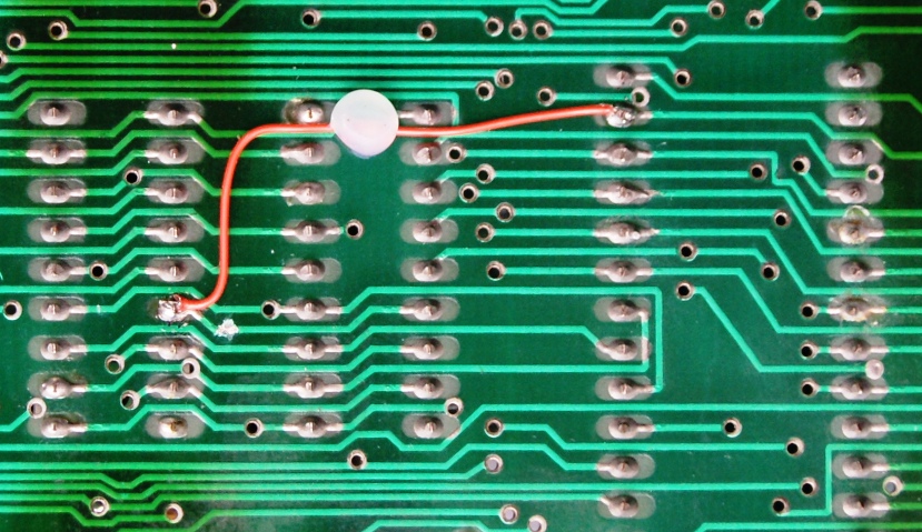